


| WORKING BAND: | 87.5 - 108 MHz |
| BANDWIDTH: | 0.2 MHz |
| GAIN: | 8.0 dBd (10.2 dBi) |
| VSWR: | ≤ 1.1:1 (-26.4 dB) |
| POLARIZATION: | Vertical or Horizontal |
| IMPEDANCE: | 50 Ohm unbalanced |
| HALF POWER BEAMWIDTH: | E-Plane - 55° H-Plane - 73° |
| LIGHTNING PROTECTION: | All metal parts DC grounded including inner conductors |
| AVAILABLE VERSION AND CODE: | AST0402335 - N - max 400W rms AST0402336 - DIN 7/16 female - max 1200W rms AST0402337 - EIA 7/8” - max 1800W rms |
| MATERIALS: | Stainless steel body, bracket and bolts Aluminum junctions |
| MOUNTING: | Directly on supporting structure |
| MOUNTING MOUNTING BRACKETS: | Included for Ø60÷114mm pipe (Ø 2.36” - 4”) |
| ICING PROTECTION: | Optional ABS radome (Code XRAST35) |
| TREATMENTS: | Aluminum componets military norms treatement (MIL-C-5541) Silver plated connector |
| PRESSURIZATION: | No |
| ANTENNA DIMENSIONS: | 2200x1600x110 mm (86.6x62.9x4.3 in)* |
| ANTENNA WEIGHT: | 14 kg (33.06 lb)* |
| WIND SURFACE: | 0.04m² (0.43 ft2) front - 0.22m² (2.36 ft2) side* |
| WIND LOAD (160 km/h and 30°C) (160 km/h and 30°C) | 0.03 kN front - 0.17 kN side* |
| SURVIVAL WIND: | 160 km/h (99.4 mph) |
| PACKING DIMENSIONS: | Box 2500x250x250mm - 15 kg* (98.4x9.8x9.8 in - 33.06 lb) |
Note: (*) Dimensions depend on working frequency.
Current values are referred to 98.00 MHz frequency.
| FREQUENCY RANGE | 87.5 ÷ 108 MHz |
| IMPEDANCE | 50 ohm |
| CONNECTOR | EIA flange according to system power rating |
| POWER RATING | The antenna system can accept any power according to requirements |
| VSWR | ≤ 1.10 in the operating channels or ≤ 1.15 throughout the frequency range Antenna system VSWR value also depending from the supporting structure |
| POLARIZATION | Vertical or Horizontal |
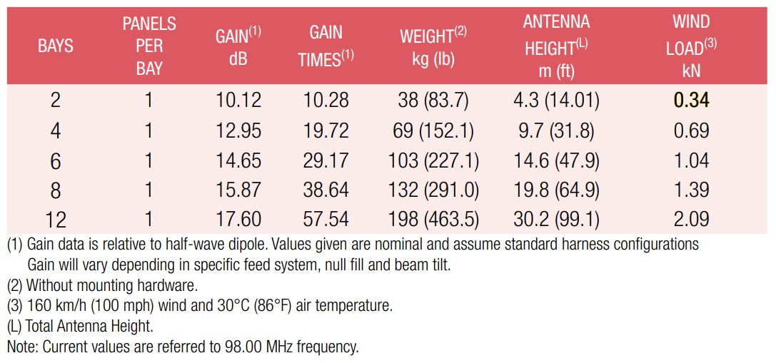
| GAIN | Refer to table |
| HORIZONTAL PATTERN | Directional |
| VERTICAL PATTERN | Null fill, beam tilt and special requirements to order |
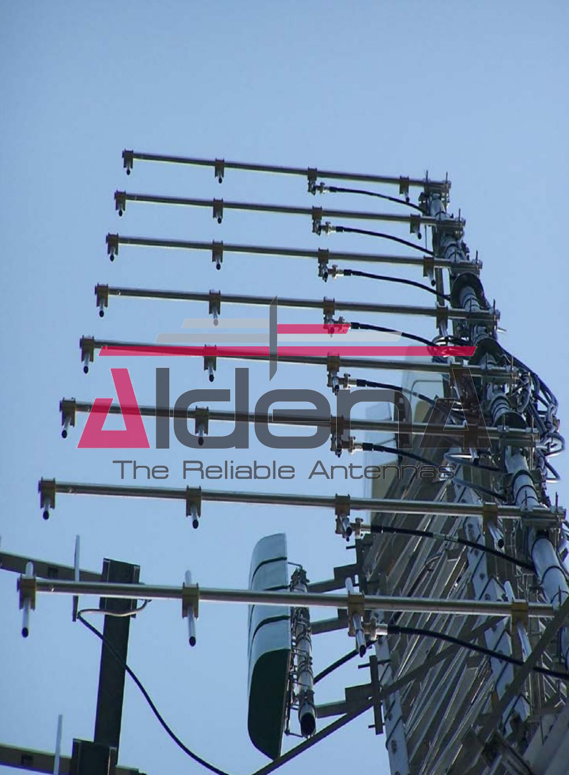
| HEIGHT OF ARRAY | Subject to number of bays |
| TOTAL NET WEIGHT | Refer to table |
| WIND LOAD | Refer to table |
| PRESSURIZABLE | No |
| MOUNTING HARDWARE | Optional mounting for side mount configuration |
| PATTERN DESIGN | Custom azimuth and elevation (beam tilt and null fill) patterns can be designed to meet specific protection/coverage requirements |
| PATTERN CERTIFICATION | Proof-of-performance factory test and pattern measurements on ALDENA test plan area |
| MOUNTING HARDWARE | Turn-key antenna delivering Tower top/side spine Special hardware/brackets |
| TRANSMISSION LINE | Transmission line system design and layout |
| COMBINERS/FILTERS | Combiners/Filters to suit requirements can be supplied |
| CALCULATION SERVICES | Coverage/interferfence simulations EM Near Field control and reduction (Environmental impact studies) |
| ON-SITE SERVICES | Site Survey and Inspection Installation/commissioning and supervisioning Drive test & EM Field strength measurements After sales maintenance |
| TRAINING | Techical training certification and consultancy |
Specifications are subject to change without notice.