


| WORKING BAND: | 87.5 - 108 MHz |
| BANDWIDTH: | 0.2 MHz |
| GAIN: | -2.15 dBd (0 dBi) |
| VSWR: | ≤ 1.12:1 (-25 dB) |
| POLARIZATION: | Circular |
| IMPEDANCE: | 50 Ohm unbalanced |
| HALF POWER BEAMWIDTH: | Omnidirectional ± 1.5 dB in free space Omnidirectional ± 2.0 dB with pole ø104mm (4”) |
| LIGHTNING PROTECTION: | All metal parts DC grounded including inner conductors |
| AVAILABLE VERSION AND CODE: | ACG0102230- N f. conn.r - max 500W rms To be tuned on field. ACG0102231- N f. conn. - max 500W rms Factory tuned. ACG0102232- DIN 7/16” f. conn. - max 1500W rms Factory tuned. ACG0102233- DIN 7/16” f. conn. - max 1500W rms To be tuned on field |
| MATERIALS: | Stainless steel |
| MOUNTING: | Directly on supporting structure |
| MOUNTING BRACKETS: | Included for Ø30÷65mm pipe (Ø1.18” - 2+1/2”) |
| TREATMENTS: | Silver plated connector |
| ANTENNA DIMENSIONS: | Min. 885x410x295 mm (34.8x16.1x11.6 in)* |
| ANTENNA WEIGHT: | 4.5 kg (9.9 lb)* |
| WIND SURFACE: | Min. 0.01m2 (0.10ft2) front - 0.04m2 (0.43 ft2) side* |
| WIND LOAD (160 km/h and 30°C) (160 km/h and 30°C) | Min. 0.01 kN front - 0.03 kN side* |
| SURVIVAL WIND: | 180 km/h (111.8 mph) |
| PACKING DIMENSIONS: | Box 1100x1100x360mm - 7kg (43.3x43.3x14.1 in - 15.4lb) |
| FREQUENCY RANGE | 87.5 ÷ 108 MHz |
| IMPEDANCE | 50 ohm |
| CONNECTOR | EIA flange according to system power rating |
| POWER RATING | The antenna system can accept any power according to requirements |
| VSWR | ≤ 1.10 in the operating channel Antenna system VSWR value also depending from the supporting structure |
| POLARIZATION | Circular |
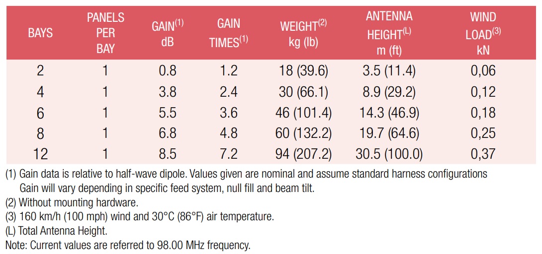
| GAIN | Refer to table |
| HORIZONTAL PATTERN | Any type according to requirement |
| VERTICAL PATTERN | Null fill, beam tilt and special requirements to order |
| OTHER FEATURES | Antenna components and feed harnesses can be optimized for channels of interest. The antenna system can be supplied in split feed configuration (two equal halves). Each half can accept full power. |
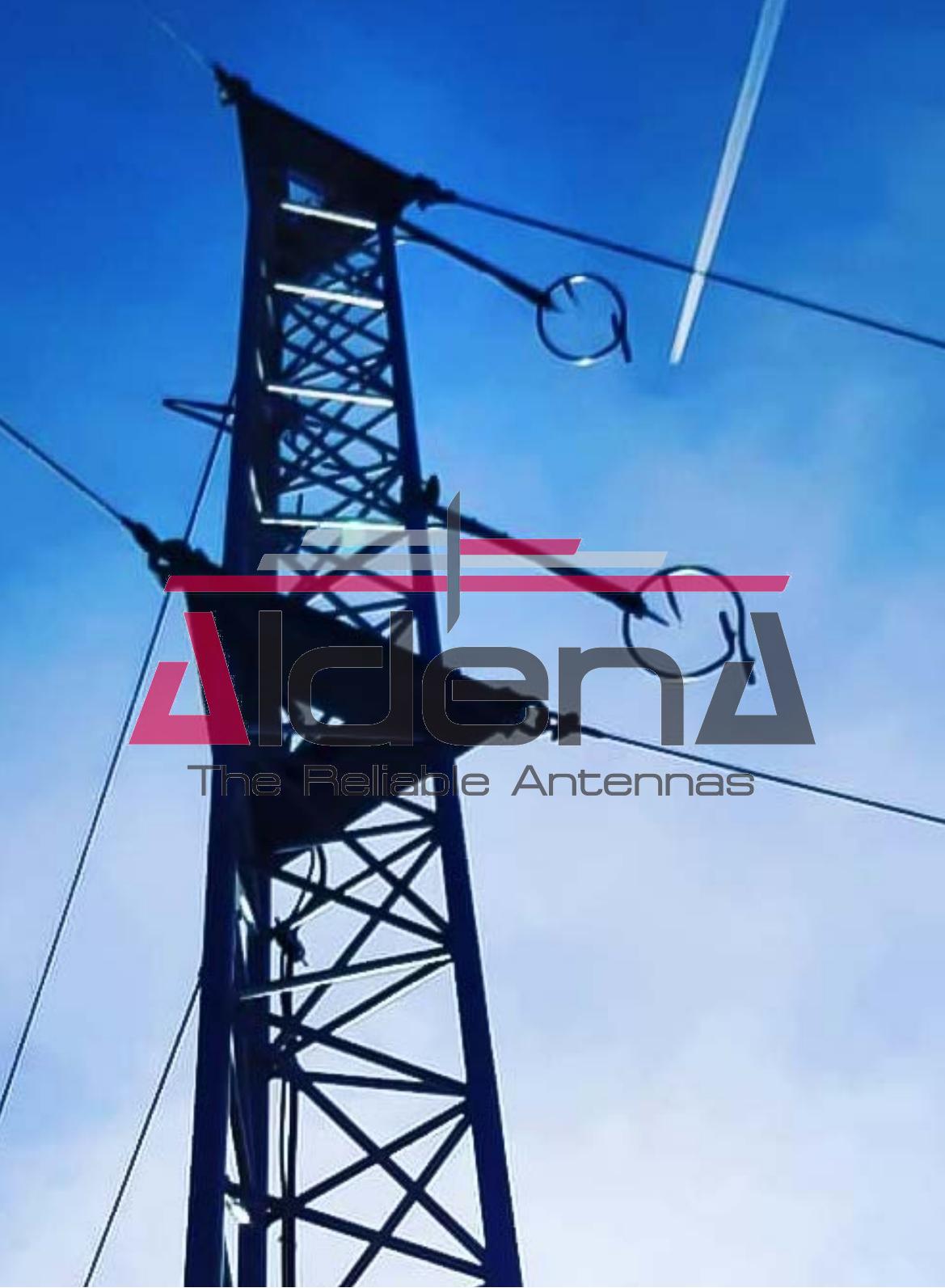
| HEIGHT OF ARRAY | Subject to number of bays |
| TOTAL NET WEIGHT | Refer to table |
| WIND LOAD | Refer to table |
| PRESSURIZABLE | No |
| MOUNTING HARDWARE | Optional mounting for side mount configuration |
| PATTERN DESIGN | Custom azimuth and elevation (beam tilt and null fill) patterns can be designed to meet specific protection/coverage requirements |
| PATTERN CERTIFICATION | Proof-of-performance factory test and pattern measurements on ALDENA test plan area |
| MOUNTING HARDWARE | Turn-key antenna delivering Tower top/side spine Special hardware/brackets |
| TRANSMISSION LINE | Transmission line system design and layout |
| COMBINERS/FILTERS | Combiners/Filters to suit requirements can be supplied |
| CALCULATION SERVICES | Coverage/interferfence simulations EM Near Field control and reduction (Environmental impact studies) |
| ON-SITE SERVICES | Site Survey and Inspection Installation/commissioning and supervisioning Drive test & EM Field strength measurements After sales maintenance |
| TRAINING | Techical training certification and consultancy |
Specifications are subject to change without notice.