All metal parts DC grounded
including inner conductors
AVAILABLE VERSION AND CODE:
ASD0102211- EIA 7/8” flange - max 5000W rms ASD0102212 - EIA 7/16 female - max 3000W rms ASD0102213- N female connector - max 800W rms ASD010221X/2 Version for 2 dipoles antenna system
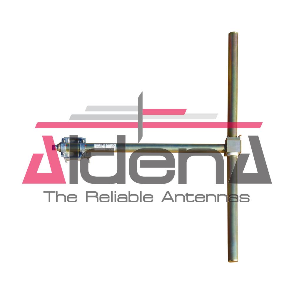
MECHANICAL DATA
MATERIALS:
Aluminium body and internal lines
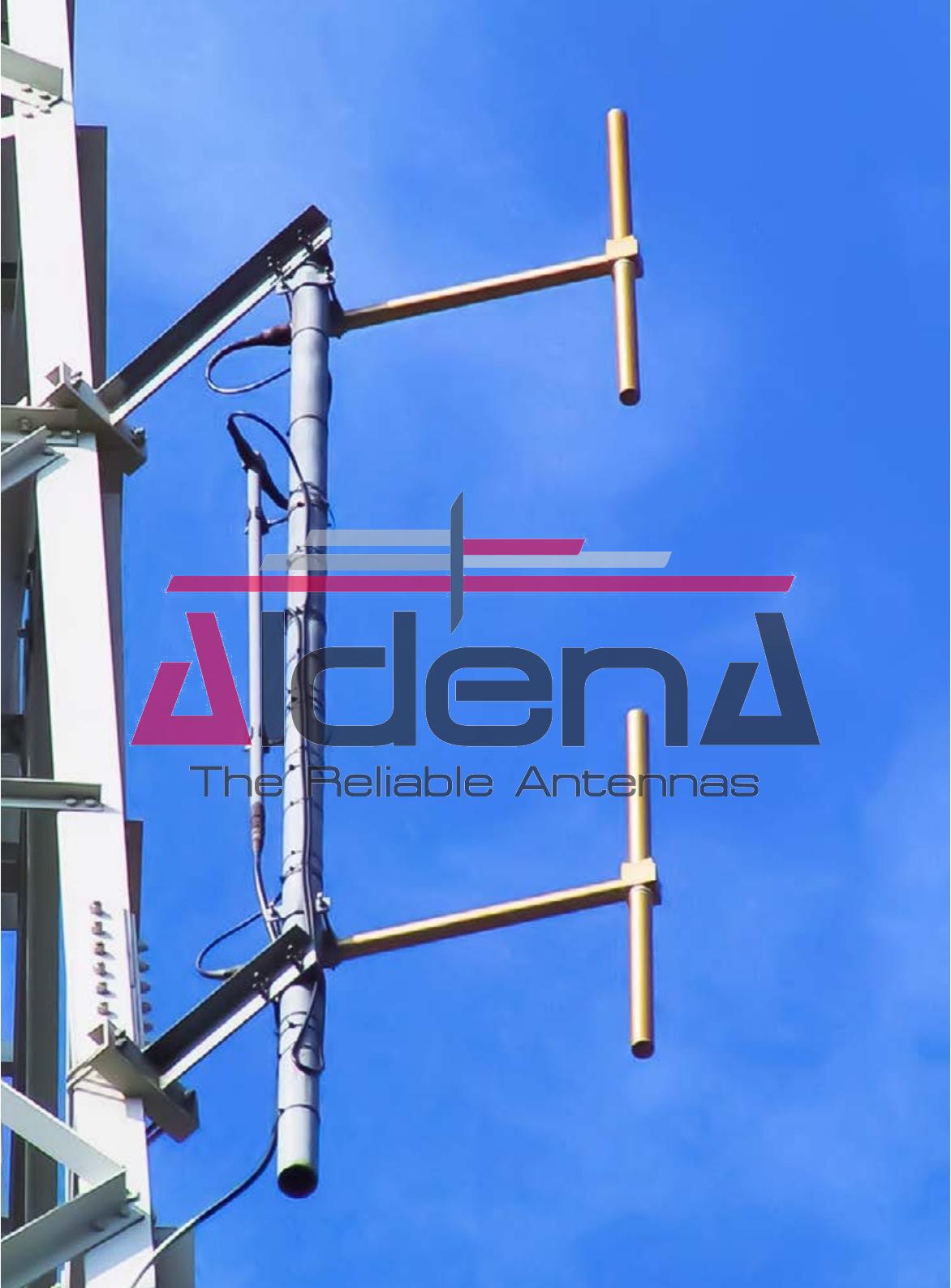
MOUNTING:
Directly on supporting structure
Safety parafil kit included
MOUNTING MOUNTING BRACKETS:
Included for Ø40÷114mm pipe (Ø1 5/8” - 4+1/2”)
ICING PROTECTION:
Optional feed point radome (code XRASD)
TREATMENTS:
Antenna body military norms treatement (MIL-C-5541)
PRESSURIZATION:
5.0 psi
ANTENNA DIMENSIONS:
1350x960x90 mm (53.1x37.8x3.5 in)
ANTENNA WEIGHT:
6.3 kg (13.8 lb)
WIND SURFACE:
0.07m2 (0.75ft2) front - 0.11m2 (1.18 ft2) side
WIND LOAD
(160 km/h and 30°C)
(160 km/h and 30°C)
0.05 kN front - 0.09 kN side
SURVIVAL WIND:
220 km/h (136.7 mph)
PACKING DIMENSIONS:
Box 1210x310x150mm - 10kg (47.6x12.2x5.9 in - 22.04lb)
ARRAY FEATURES
Omnidirectional patterns
Equal or unequal power distribution system
Configurable for specific azimut and elevation pattern
Suitable for multiplexing many channels
ARRAY ELECTRICAL DATA
FREQUENCY RANGE
87.5 ÷ 108 MHz
IMPEDANCE
50 ohm
CONNECTOR
EIA flange according to system power rating
POWER RATING
The antenna system can accept any power according to requirements
VSWR
≤ 1.17 in the operating channels or
≤ 1.27 throughout the frequency range
Antenna system VSWR value also depending from the
supporting structure
POLARIZATION
Vertical
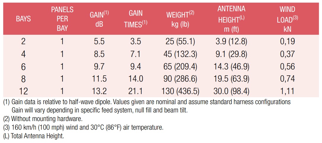
GAIN
Refer to table
HORIZONTAL PATTERN
Omnidirectional
VERTICAL PATTERN
Null fill, beam tilt and special requirements to order
OTHER FEATURES
Antenna components and feed harnesses can be
optimized for channels of interest.
ARRAY MECHANICAL DATA
HEIGHT OF ARRAY
Subject to number of bays
TOTAL NET WEIGHT
Refer to table
WIND LOAD
Refer to table
PRESSURIZABLE
Optional
MOUNTING HARDWARE
Optional mounting for side mount configuration
ARRAY TECHNICAL DATA
ANTENNA DIMENSIONAL DETAILS
OPTIONS & SERVICES
PATTERN DESIGN
Custom azimuth and elevation (beam tilt and null fill) patterns can be designed to meet specific protection/coverage requirements
PATTERN CERTIFICATION
Proof-of-performance factory test and
pattern measurements on ALDENA test plan area
MOUNTING HARDWARE
Turn-key antenna delivering
Tower top/side spine
Special hardware/brackets
TRANSMISSION LINE
Transmission line system design and layout
COMBINERS/FILTERS
Combiners/Filters to suit requirements can be supplied
CALCULATION SERVICES
Coverage/interferfence simulations
EM Near Field control and reduction (Environmental impact studies)
ON-SITE SERVICES
Site Survey and Inspection
Installation/commissioning and supervisioning
Drive test & EM Field strength measurements
After sales maintenance
TRAINING
Techical training certification and consultancy
Specifications are subject to change without notice.
GET IN TOUCH
CONTACTS
ALDENA TELECOMUNICAZIONI Srl Via per Vighignolo 6/8 20019 Settimo Milanese (MI) Italy
This website uses cookies to improve your experience. We'll assume you're ok with this, but you can opt-out if you wish. Cookie settingsACCEPTMore Informations
Privacy & Cookies Policy
Privacy Overview
This website uses cookies to improve your experience while you navigate through the website. Out of these cookies, the cookies that are categorized as necessary are stored on your browser as they are essential for the working of basic functionalities of the website. We also use third-party cookies that help us analyze and understand how you use this website. These cookies will be stored in your browser only with your consent. You also have the option to opt-out of these cookies. But opting out of some of these cookies may have an effect on your browsing experience.
Necessary cookies are absolutely essential for the website to function properly. This category only includes cookies that ensures basic functionalities and security features of the website. These cookies do not store any personal information.
Any cookies that may not be particularly necessary for the website to function and is used specifically to collect user personal data via analytics, ads, other embedded contents are termed as non-necessary cookies. It is mandatory to procure user consent prior to running these cookies on your website.