


| WORKING BAND: | 87.5 - 108 MHz |
| BANDWIDTH: | VHF band FM |
| GAIN: | - 0.25 dBd (1.95 dBi) |
| VSWR: | ≤ 1.27:1 (-18.5 dB) |
| POLARIZATION: | Circular |
| IMPEDANCE: | 50 Ohm unbalanced |
| HALF POWER BEAMWIDTH: | Omnidirectional ± 1.5 dB in free space Omnidirectional ± 2.0 dB with pole ø104mm (4”) |
| LIGHTNING PROTECTION: | All metal parts DC grounded including inner conductors |
| AVAILABLE VERSION AND CODE: | ACF0202218 - EIA 1+5/8” flange - max 15000W rms |
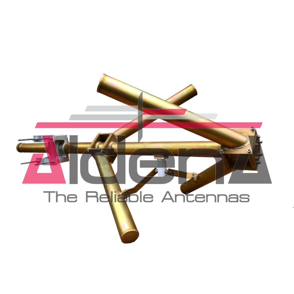
| MATERIALS: | Aluminum dipoles and body version and internal lines |
| MOUNTING: | Directly on supporting structure Safety parafil kit included |
| MOUNTING BRACKETS: | Included for Ø90÷150mm pipe (Ø3.54” - 5.9”) |
| ICING PROTECTION: | Feed point radome |
| TREATMENTS: | Dipoles and antenna body military norms treatement (MIL-C-5541) Silver plated lines and connector |
| PRESSURIZATION: | 5.0 psi |
| ANTENNA DIMENSIONS: | 1950x1160x1160 mm (76.7x45.6x45.6 in) |
| ANTENNA WEIGHT: | 33.5 kg (73.8 lb) |
| WIND SURFACE: | 0.2m2 (2.15ft2) front - 0.34m2 (3.65 ft2) side |
| WIND LOAD (160 km/h and 30°C) (160 km/h and 30°C) | 0.16 kN front - 0.27 kN side |
| SURVIVAL WIND: | 220 km/h (136.7 mph) |
| PACKING DIMENSIONS: | Box 2000x360x300mm - 40kg (78.7x14.2x11.8in - 88.18lb) |
| FREQUENCY RANGE | 87.5 ÷ 108 MHz |
| IMPEDANCE | 50 ohm |
| CONNECTOR | EIA flange according to system power rating |
| POWER RATING | The antenna system can accept any power according to requirements |
| VSWR | ≤ 1.17 in the operating channels or ≤ 1.25 throughout the frequency range Antenna system VSWR value also depending from the supporting structure |
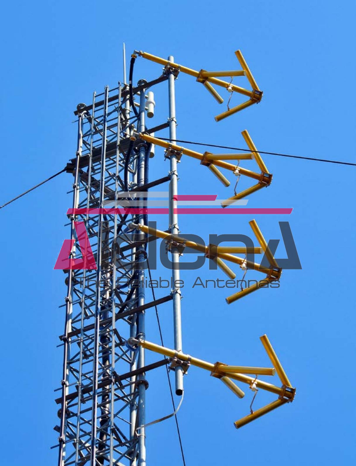
| POLARIZATION | Vertical |
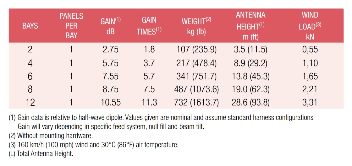
| GAIN | Refer to table |
| HORIZONTAL PATTERN | Omnidirectional |
| VERTICAL PATTERN | Null fill, beam tilt and special requirements to order |
| OTHER FEATURES | Antenna components and feed harnesses can be optimized for channels of interest. |
| HEIGHT OF ARRAY | Subject to number of bays |
| TOTAL NET WEIGHT | Refer to table |
| WIND LOAD | Refer to table |
| PRESSURIZABLE | No |
| MOUNTING HARDWARE | Optional mounting for side mount configuration |
| PATTERN DESIGN | Custom azimuth and elevation (beam tilt and null fill) patterns can be designed to meet specific protection/coverage requirements |
| PATTERN CERTIFICATION | Proof-of-performance factory test and pattern measurements on ALDENA test plan area |
| MOUNTING HARDWARE | Turn-key antenna delivering Tower top/side spine Special hardware/brackets |
| TRANSMISSION LINE | Transmission line system design and layout |
| COMBINERS/FILTERS | Combiners/Filters to suit requirements can be supplied |
| CALCULATION SERVICES | Coverage/interferfence simulations EM Near Field control and reduction (Environmental impact studies) |
| ON-SITE SERVICES | Site Survey and Inspection Installation/commissioning and supervisioning Drive test & EM Field strength measurements After sales maintenance |
| TRAINING | Techical training certification and consultancy |
Specifications are subject to change without notice.